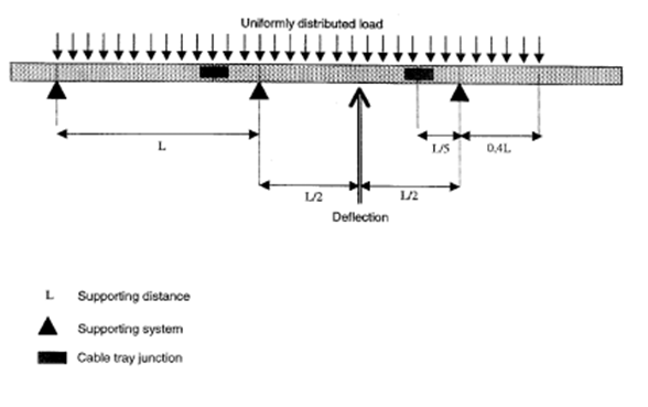
Cable Tray Support Distance

Cable Tray Ladder Trunking Wire Basket Installation Guidelines Cable Tray Wire Baskets Cable

Loading Performance Legrand

Practices For Grounding And Bonding Of Cable Trays

Cable Tray Sample Layout Cable Tray Cable Trays Cable

Cable Support Systems Design And Installation Ee Publishers

Typical Design Philosophy Of Cable Trays For Power Plant Cable Tray Cable Trays Cable

Below is a preview of the nec.
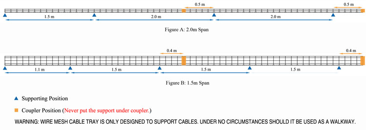
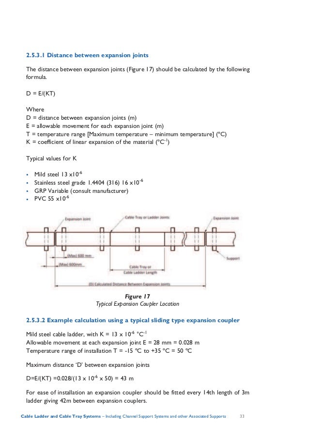
Cable tray support distance. This classification is based on the working load the total weight of the cables and the support span the distance between supports. 6 cable ladder and cable tray systems including channel support systems and other associated supports definitions and abbreviations accessory component used for a supplementary function e g. The 2014 nec requires the labels to be visible after installation and spaced no further than 10 ft. Support load calculation per iec 61537.
A generic guideline developed by the cable tray institute indicates that cable trays should not be filled in excess of 40 50 of the inside area of the tray or of the tray s maximum weight based on the cable tray specifications. To join two components together clamp or fix to walls ceilings or other supports covers and cable retainers associated supports bespoke supports for cable tray and cable ladder other than bs 6946 channel. Cable load working load the cable load or the working load is the total weight of the cables to be placed in the tray. A cable tray fitting which changes the direction in the same plane.
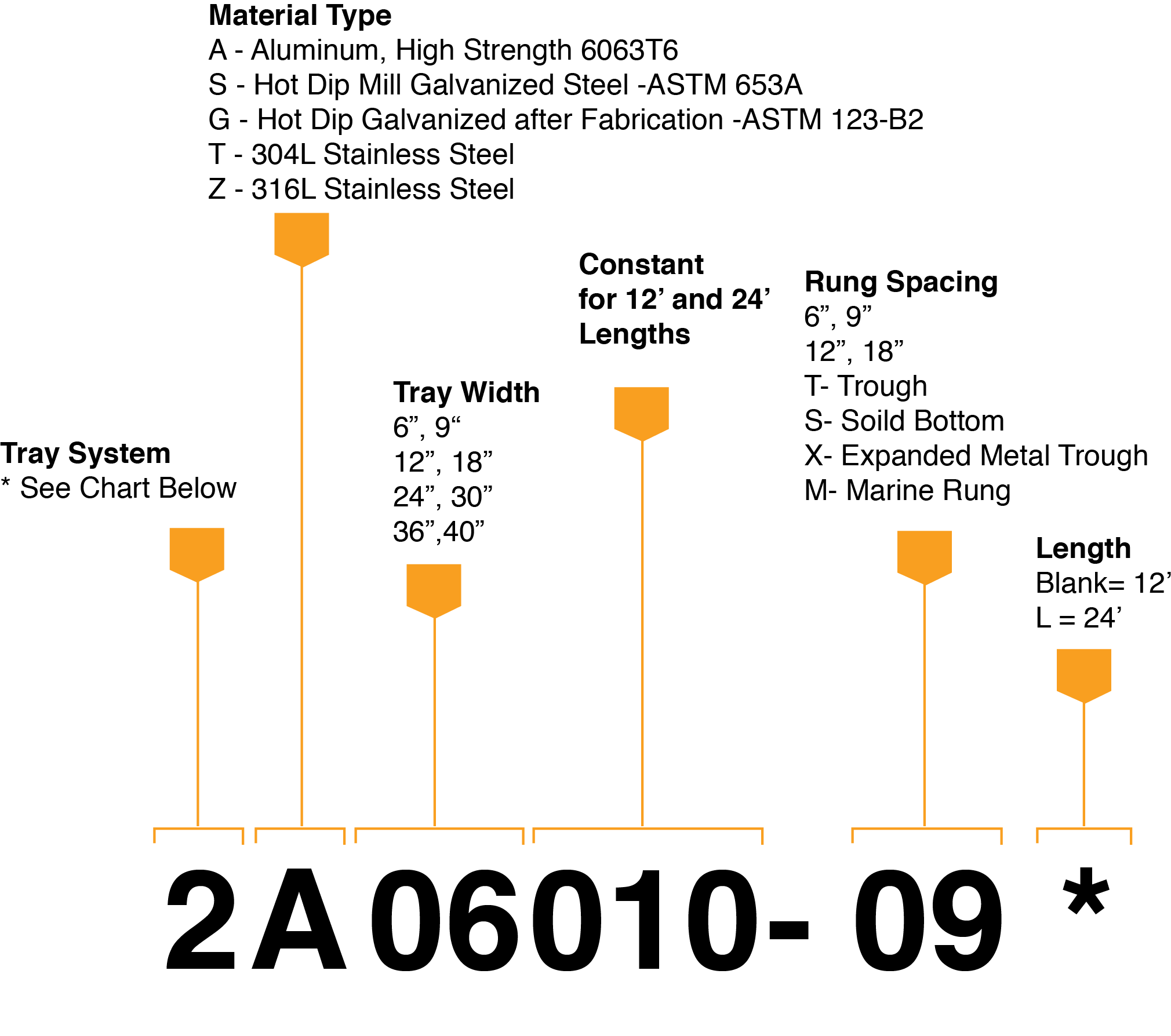
The nema classifications for cable tray were established to simplify and standardize the specification of cable tray. A cable tray fitting which is suitable for joining cable trays in three directions at 90 degree intervals in the same plane. Trays that meet nema specs support 3 4 5 or 6 inch fills and widths from 6 to 36 inches. The length between support positions will change depending on the cable design size materials and weight.
One or more spans iec 61537 7 3i for installations with more than one span it is important to notice that the loading capacity is not the same form one end to the other. Metallic cable tray system. See the actual nec text at nfpa org for the complete code section. The label ensures that the service entrance conductors can be traced throughout the cable tray.
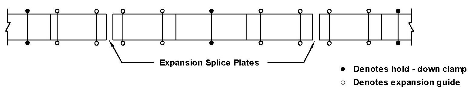
Evenly distributed load 2 x point load support distance. There are cable trays available to meet all nema requirements with spans of 8 12 16 or 20 feet and loading capacities of 50 75 or 100 lbs ft. Mushroom headed steel roofing bolts and nuts shall be used for the installation and coupling of trays. Longer spans mean fewer supports which translates to lower installed costs.
Cable trays shall be supported by mild steel galvanized brackets at regular intervals of 1 2mm maximum and at 255mm from bends and tees. For example an mdpe sheathed cable will be stiffer and therefor require a greater distance between supports than the same lsoh cable to achieve the same 2 deflection sag.
Design Consideration We Follow Powersolution
Safe Working Load Swl Bonet Cable Tray

Info Trayload

Procedure For Instrument Branch Cable Tray Installation Paktechpoint
Wireways Selection Guide Engineering360
Products Chalfant
Http Www Sourceiex Com Catalogs Chapter 2014 20cable 20support 20systems Pdf

Maybe Planks In Rafters To Support Cable Trays Or Loops Cathedral Ceiling Building A House Roof Framing
Cable Tray Safe Working Load Test Swl Electrical Safety

Cable Tray Bracket Dimensions Google Search Cable Tray Bracket Tray
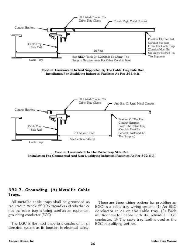
Cable Tray Manual
Http Emeraldsteeluae Com Wp Content Uploads 2018 02 Esi Cable Tray1 Pdf

Rack Wall Tv Stand Modern Tv Wall Units Tv Wall

Rack Wall Tv Stand Wall Mounted Tv Swivel Tv Stand

Linear Heat Detection Lhd Is A Line Type Form Of Fixed Temperature Heat Detection Used In Common Commercial And Industrial Envi Fire Linear Electrical Cables

Backbone Cabling Is The Inter Building And Intra Building Cable Connections In Structured Cabling Between Entrance Facilities Equipment Rooms And Telecommunica

Structured Cabling Installation Practices Part Three Installing A Structured Cabling System Dintek Articles Dintek Electronic Ltd
Mesh Cable Tray System Hdmann Cable Management System
Https Encrypted Tbn0 Gstatic Com Images Q Tbn 3aand9gctuksd Ebxog3081izgmiq3vxydb3tnh06osnyl F09g0kgqnny Usqp Cau

Cable Tray And Trunking For Electricians Page 1 Help Me Math Is Fun Forum

Construction Resume Writing Tips Customer Service Resume Resume Resume Templates

Knee Braces Provide Strong Tree House Support Tree House Tree House Diy Diy Swing

Welcome To Syarikat Lanric Industries Sdn Bhd

Seatcraft Omega Leather Gel Home Theater Seating Power Recline Multimedia Sofa With Adjustable Powered Headrests And Folddow In 2020 Home Theater Seating Recliner Sofa

Products Bvs Niedax Norge Niedax Cable Tray Systems Bvs Niedax Norway Is A Successful Norwegian Based Supplier Of Cable Management Solutions For The Offshore Und Tunnel Market

Understanding Cable Trays

We Continue Our Series On Desirable Offshore Motorboats For Those Retiring From Sailboats With A Design Analysis By Aac Sailboat Design Analysis Motor Boats

Bicsi Official Group Groups Linkedin Cable Tray Award Winning Data Center

How To Recognize The Overloaded Cable Trays Cable Trays Cable Tray Tray

Pin On Architecture Design

Cable Trays An Overview Sciencedirect Topics
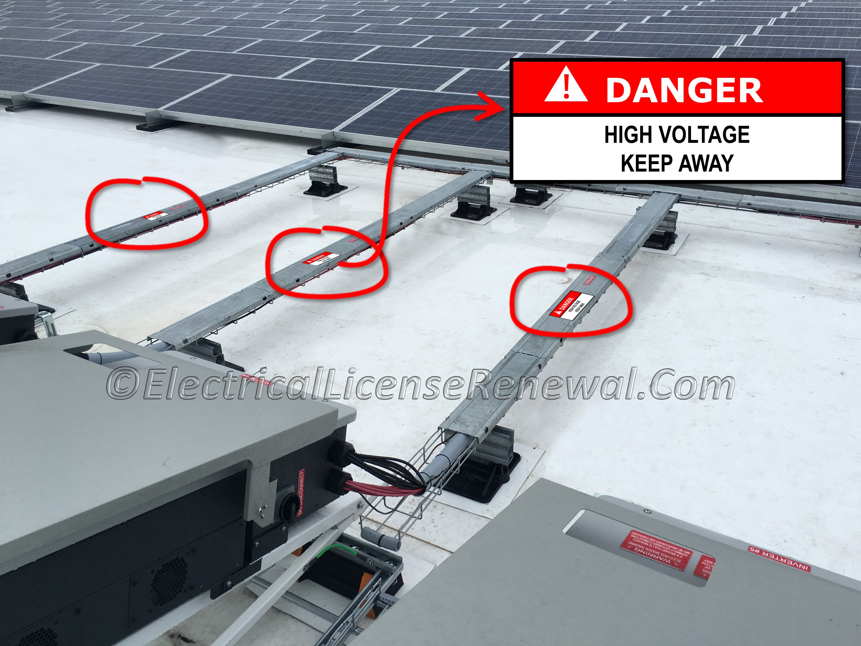
392 18 H Cable Trays Marking
Beama Best Practice Guide To Cable Ladder Cable Tray Systems

High Tech Podium Pdx20 Floor Plans Modern Furniture
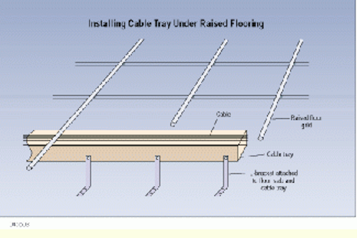
Install Cable Tray Under Raised Flooring Cabling Installation Maintenance

33 5 X45 Amazing 2bhk East Facing House Plan As Per Vastu Shastra Autocad Dwg And Pdf File Details Cadbul In 2020 Residential House House Layouts Open House Plans

Industrial Cable Trays Channels Snap Track Cable Tray Techline Mfg

Steel Cable Tray Forming Machine Cable Tray Roll Forming Steel
Https Sites2 Uol Edu Pk Journals Index Php Pakjet Article Download 113 31
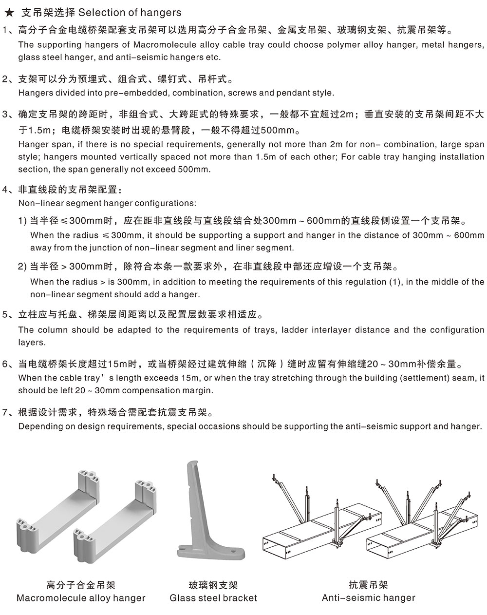
Macromolecule Alloy Cable Tray Chs

Lv To Hv Separation On Cable Support Tray Electric Power Transmission Distribution Eng Tips

Electrical Room Cable Trays Cable Tray Installation Ladder

